
         |
I have a dead Bird slug which was used mainly for taking up space on my bench. This slug came with a Bird 43 I had aquired and it was known dead. As I neither have nor repair anything that would need a 5Kw slug, it really wasn't that big of a deal. Not to mention I am not setup for 5Kw of RF. 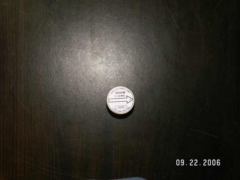 After a few days of searching the 'net, I finally came across K5LAD's page on repairing Bird slugs. As I read the scant pages dealing with the dissassembly and repair of Bird slugs, I decided to join in the documentation effort and record my endevors on dismantling and (hopefully) repairing this slug. So begins my next project.... The label is held in place by adhesive, which I soaked in gasoline for about 10 hours. 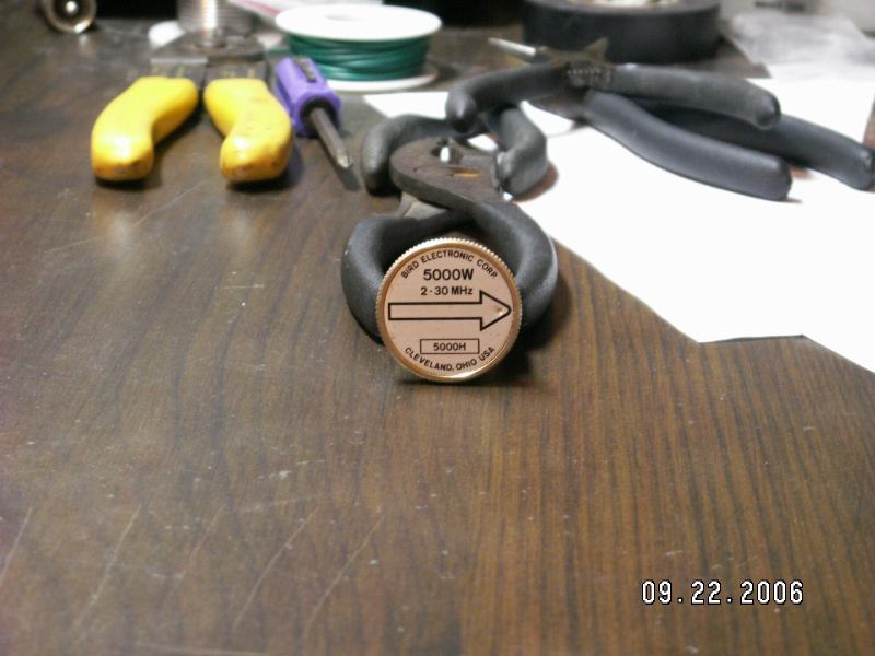
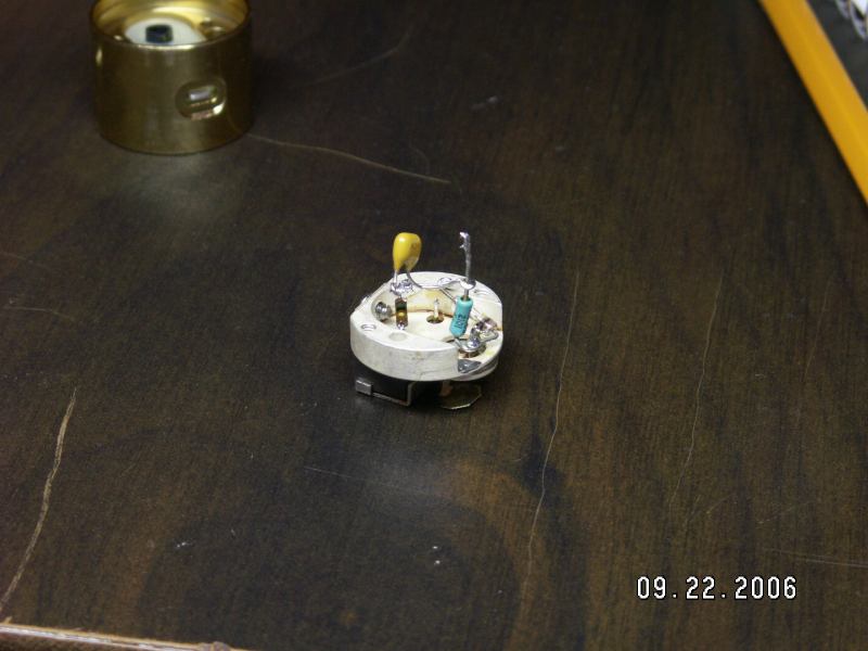
 Yeah, I know...that's dangerous, and I DO NOT recommend using any type of flammable, explosive, or otherwise dangerous liquids to remove this adhesive. OK, with that disclaimer out of the way, let's continue. After the soaking, I was able to use a razor knife to remove the label. Inside, you'll find a single machine screw and a hole. The hole leads to a varable resistor (in this model) to adjust the output of the RF coupling circuit further inside the slug. 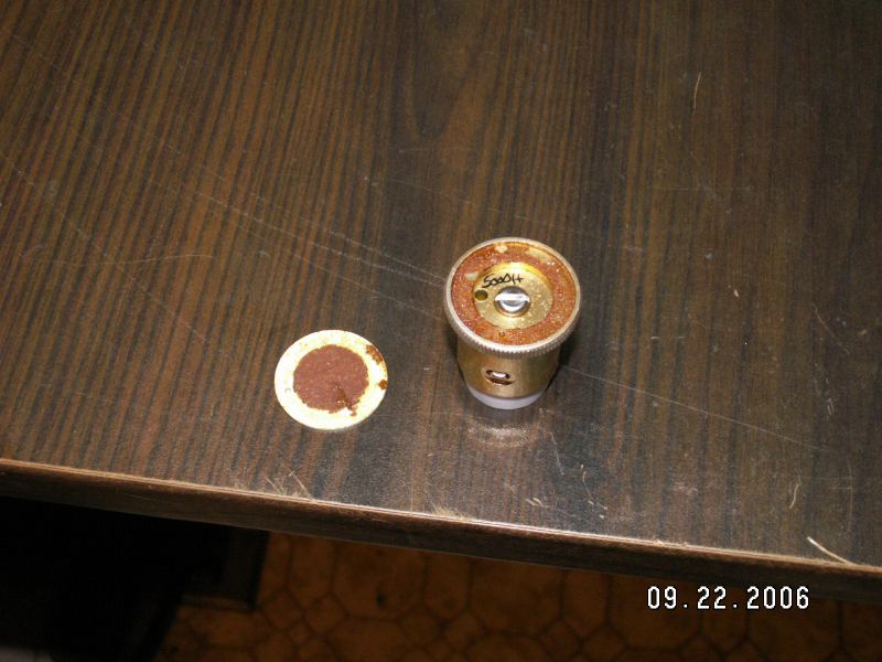 Removal of the screw will allow you to remove the top piece of the slug. Inside, you will find a varable resistor soldered to two points. The closest point (in these pictures) goes to the side connectors, and then to the meter movement when the slug is inserted into the wattmeter. 

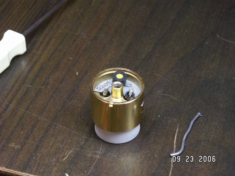 PLEASE NOTE....I did not think to remember which way I was removing parts from this slug. After I had the entire thing dissassembled on my bench, I realized I wasn't paying attention to how they were placed. Note the varable resistor is across from the notch in the main body. With the top of the slug up, and the notch closest to you, the direction of the slug is from right to left. In this position, the arrow will point left. Some slugs have an indention within the arrowhead on the label which corresponds to a like indention in the top body. This particular slug did. After I removed the varable resistor and insulator, I proceded to remove the teflon cover off the bottom of the slug. This cover fits into a groove on the ID of the slug body, and can be a little tricky to remove. I used a little bit of pressure in the middle of the cover, and a small flathead screwdriver. 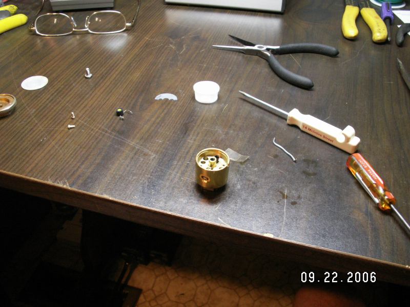 Turning the slug upside down reveals the pickup coil and something I am not quite sure about. Best guess is another pickup, as this is a high-power slug. The coupling direction in the second picture is from lower-left to upper-right. 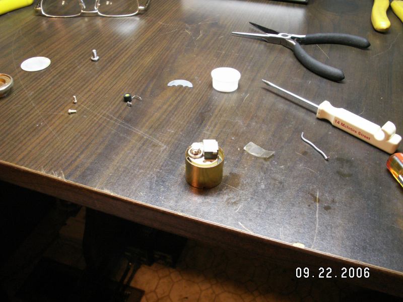
 After the varable resistor and insulator is removed from the top, you will see 2 more machine screws. These hold the pickup coil. Removal of these will allow you to remove the pickup coil assembly from the housing. 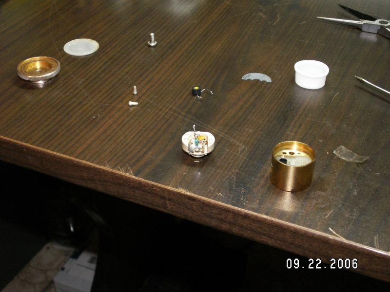 After removal of the coil assy, another machine screw will present itself from the bottom of the slug. This screw holds the output connector assembly. Removal of this assembly is quite straight-forward, as the rest of the slug has been. The output connector itself is a single piece of metal, held in place by plastic insulators on top and bottom, and a screw in the middle. 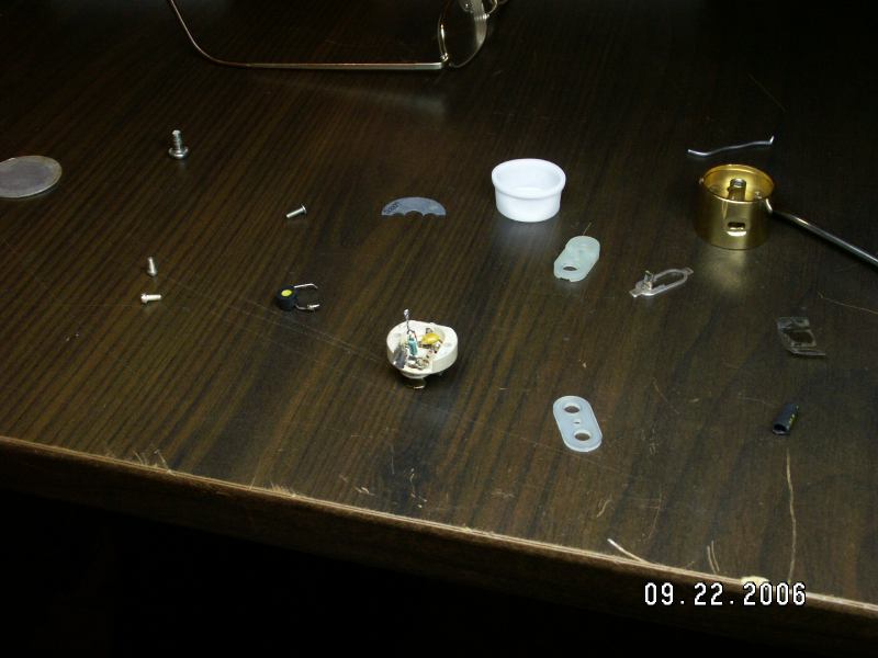

 After removal and visual check of all parts, I began testing. I removed connections to the pickup coil to test all parts individually. 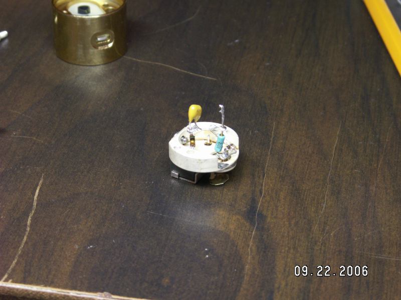
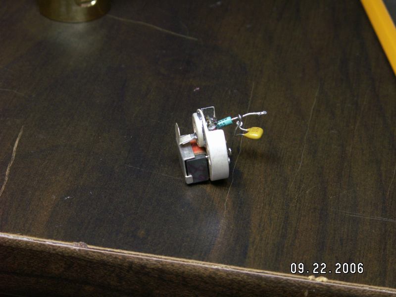
 Here are some better pictures of the pickup coil on the bottom of the slug. In both pictures, RF flow would be going into the table. 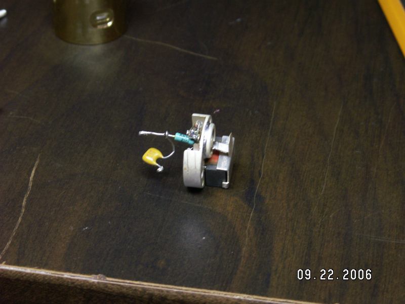
 Here is my drawing of what I found the circuit to be in this slug.  After testing all parts, I concluded they were all within tolerance. Upon further inspection, I found the coil had a bit of solder that was touching on the case. I believe this is the reason for the slug not working. I personally don't have anything capable of moving the meter very far with this slug, but I was able to test it against my 1000H slug. Seems to work quite well now. 
 For those interested, HERE is the original patent for the Bird Wattmeter, as filed September 16, 1958 by James R. Bird and Henry J. Calderhead. |
 |
Today is Previous Page Home Page |
 This site  |